


Cookies help us deliver our services. By using our services, you agree to our use of cookies.
Chapter 6. MIL-STD-1760: The Weapons Store Interface
6.1 Overiew
MIL-STD-1760 (Aircraft/Store Electrical Interconnection System) is a specialized application of MIL-STD-1553 designed specifically for "smart stores" including weapons, pods, and auxiliary fuel tanks attached to an aircraft.
While the data layer is identical to MIL-STD-1553B (1 Mbps, Manchester encoded, Command/Response), MIL-STD-1760 adds strict rules to ensure safety and interoperability between the aircraft (the "Station") and the weapon (the "Store").
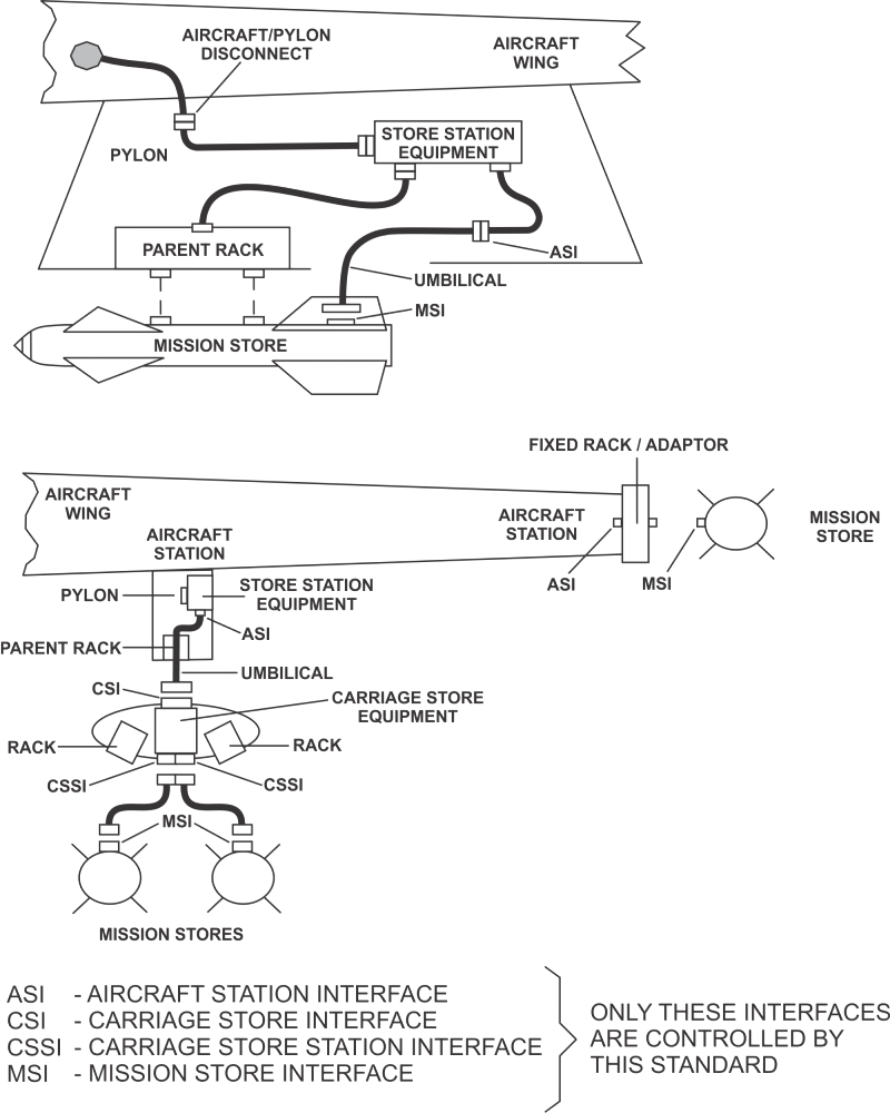
Figure 17 - Aircraft-store Configuration Examples
6.2 Key Differences from Standard 1553
While the physics are the same, the application of the protocol is much stricter in a weapons environment.
6.2.1 Fixed Geographical Addressing
In a standard 1553 system, RT addresses might be assigned via dip switches or software. In MIL-STD-1760, the address is determined geographically by the connector.
- Concept: The Aircraft Station Interface (ASI) connector has specific address pins wired to logic ground or open.
- Result: When a missile is loaded onto "Station 1" (e.g., Left Wing Tip), it automatically assumes RT Address 1. This is a safety-critical feature: it prevents the mission computer from accidentally firing the weapon on the right wing when it intended to fire the one on the left.
- Address Latching: The RT address must be determined solely by the discrete connector pins. It must be latched within 10 ms of power application. Once latched, the address must not change, even if the connector pins subsequently change state (due to vibration or intermittent contact).
- No Software Assignment: The address must be hardware-derived. It cannot be assigned or overridden by internal software, ensuring the weapon always matches the physical station it is attached to.
- Wetting Current: The interface must provide 5 mA of wetting current per address line to ensure reliable contact in harsh, oxidizing environments.
6.2.2 Message Integrity (Checksums)
Because releasing a weapon is irreversible, the standard 1553 odd parity bit is not considered sufficient for data integrity. MIL-STD-1760 mandates additional data protection:
- Header Word: The first data word often defines the user protocol.
- Checksum Word: Critical messages must include a Checksum as the final data word. The RT (Weapon) must calculate the checksum of the received data and compare it to this word before executing a command (like "Arm" or "Fire").
6.2.3 Restricted Mode Codes
To prevent unpredictable behavior during combat, Dynamic Bus Control is strictly forbidden. The Aircraft is always the Bus Controller; the Weapon is always the Remote Terminal.
6.3 Electrical Requirements
The electrical environment for a weapon store is harsher than the internal avionics bay.
- Complex Cabling: The signal must travel from the Mission Computer, through the wing wiring, into the pylon, through an umbilical cable, and finally into the weapon.
- Drive Power: To ensure signal integrity through these multiple connector matings and long stubs, the transceiver must be capable of driving the bus with robust signal amplitude. The standard requires a minimum output of 20.0 Volts peak-to-peak (compared to 18V for standard 1553B).
6.4 The Holt Advantage: MIL-STD-1760 Solutions
Designers of MIL-STD-1760 stores often face a critical timing challenge: the weapon's interface must be active and responsive to the aircraft almost immediately upon power-up, often before the store's internal host processor has finished booting. Furthermore, the harsh electrical environment requires specialized handling of address inputs.
Holt Integrated Circuits offers a complete ecosystem of solutions to address these challenges.
6.4.1 Instant-On Readiness (Mamba, HI-6130, HI-2130, HI-6300)
The standard requires a store to respond with a "Busy" status within 150ms of power-up. Waiting for a microcontroller to boot and configure the 1553 chip often takes too long.
- The MODE1760 Pin: Both the Mamba Family and the HI-6300 IP Core (for FPGA implementations) feature a dedicated hardware input pin. When asserted at power-up, the device automatically configures itself as an RT, sets the Busy bit, and begins responding—requiring zero software intervention.
- Auto-Initialization (EEPROM): The HI-6130, HI-2130, and MAMBA device family (HI-6135, HI-6136, HI-6137, HI-6138, HI-6139) can all automatically load their configuration (RT Address, interrupt settings, etc.) from a dedicated external EEPROM. This ensures the terminal will configure itself to be fully functional and compliant the instant power is applied.
6.4.2 Address Latching & Wetting Current (HI-8427)
A unique requirement of MIL-STD-1760 is the Aircraft Station Interface (ASI) connector, which defines the RT address using physical pins.
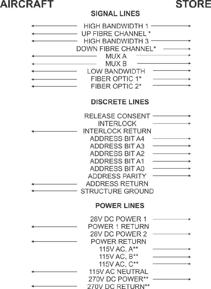
Figure 18 - MIL-STD-1760 ASI Interface Pinout
(Note: MUX A and MUX B are the MIL-STD-1553 buses. ADDRESS BITS, ADDRESS PARITY AND ADDRESS RETURN are the MIL-STD-1553 address lines.)
The mission store shall provide excitation signals with the following characteristics:
Open circuit (logic 1) voltage:
- Minimum voltage of 4.0 V dc
- Maximum voltage of 31.5 V dc
- Rise and fall times of applied voltage shall not exceed 10 milliseconds when measured with a resistive load.
Logic 0 current:
- Minimum current of 5.0 milliamperes dc
- Maximum current of 100 milliamperes through each address bit and parity connection
- Maximum current of 600 milliamperes through the address return connection
- Rise and fall times of applied current shall not exceed 10 milliseconds when measured with a resistive load.
The Challenge: The address lines must be "latched" at power-up to prevent changes during flight vibration. Additionally, the interface must provide 5 mA of wetting current per pin to burn through oxidation on the connector contacts.
The Solution (HI-8427): The HI-8427 is a discrete-to-digital sensor specifically designed for this task.
- It provides the required 5 mA wetting current source for the address lines.
- It acts as a robust interface between the connector and the digital logic.
- When paired with a Holt Protocol IC (like the MAMBA Family), the protocol chip performs the required address latching at power-up using the stable signals provided by the HI-8427.
6.4.3 Transceivers
As noted in Section 6.3, the transceiver must drive a 20V p-p signal. Holt MIL-STD-1553 transceivers (integrated in MAMBA device family (HI-6135, HI-6136, HI-6137, HI-6138, HI-6139) and HI-2130 or standalone like HI-25850) are fully compliant with this higher drive requirement.
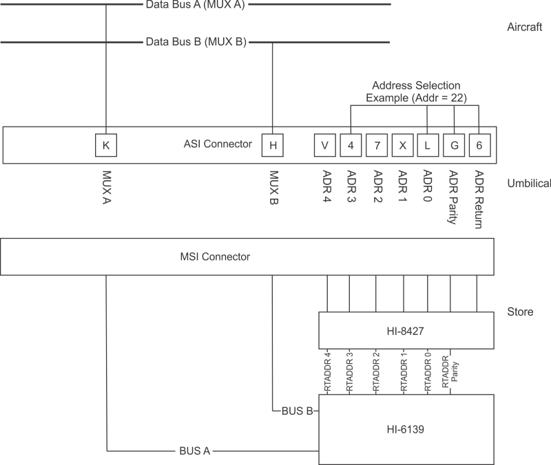
Figure 19 - MIL-STD-1760 Interface Concept
(Note: Diagram showing Aircraft Station Interface (ASI) connecting to Mission Store Interface (MSI), featuring the HI-8427 for address sensing and a HI-6139 Mamba for the bus interface.)