


Cookies help us deliver our services. By using our services, you agree to our use of cookies.
Chapter 2. The 1553 Bus Architecture
2.1 Bus Topology
The MIL-STD-1553B bus features a linear, multi-drop topology. Unlike Ethernet hubs or star networks, 1553 consists of a main bus cable with multiple devices connected via "stubs."
The architecture is defined by three primary physical elements:
- Main Bus: The backbone of the system, consisting of a shielded twisted pair transmission line (70-85 Ω).
- Stubs: The connections between the main bus and the terminal devices.
- Terminators: Resistors placed at both ends of the main bus to prevent signal reflections.
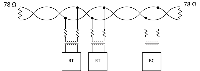
Figure 3 - Linear Bus Topology showing a single MIL-STD-1553 Bus
(Note: A linear topology features a continuous backbone with short taps (stubs). It does not fan out like a star network.)
2.2 Redundancy
To ensure mission reliability, the standard mandates a Dual-Redundant architecture. This consists of two separate buses, Bus A (Primary) and Bus B (Secondary).
- Operation: While both buses are physically present and connected to every device, only one bus is active at any given time.
- Failover: The Bus Controller manages traffic and can switch to the backup bus if faults are detected on the primary line.
- Holt Advantage: All Holt Integrated Circuit’s RTs (like the HI-6138) automatically handle status reporting for both buses simultaneously, simplifying the software overhead required to manage redundancy.

Figure 4 - Dual Redundant Architecture
(Note: Both Bus A and Bus B connect to every terminal but operate independently.)
2.3 Terminal Types
The standard defines three distinct types of terminal devices that can reside on the bus.
2.3.1 Bus Controller (BC)
The Bus Controller (BC) is the "master" of the data bus. There is only one active BC on the bus at any time. Its responsibilities include:
- Initiating all data transfers (Command/Response protocol).
- Monitoring the status of all Remote Terminals.
- Managing error recovery.
Holt Solution: The HI-6130 and HI-6131 are fully integrated terminals that can operate as a Bus Controller, Two Remote Terminals, and Bus Monitor. They handle the entire protocol state machine, allowing the host processor to simply configure the device, load data buffers and let the Holt IC execute the complex message schedules automatically. In Remote Terminal Mode, once configured, bus response timing and data buffering is handled without host processor intervention.
2.3.2 Remote Terminal (RT)
The Remote Terminal (RT) is the most common device on the bus. Up to 31 distinct RTs can be connected to a single 1553 system. RTs are the interfaces for subsystems—sensors, displays, actuators, and radios—allowing them to communicate with the main mission computer.
An RT is essentially a "slave" device; it never transmits unless commanded to do so by the Bus Controller. It listens for commands containing its unique address and responds with a Status Word and relevant Data Words.
Holt Solution: Holt offers the industry’s widest range of RT solutions.
Mamba Family (HI-6135, HI-6136, HI-6137, HI-6138, HI-6139): Compact, highly integrated Terminals featuring a fast 40MHz SPI host interface.
HI-2130: A unique solution that integrates the isolation transformers directly into the IC package, drastically reducing the board footprint required for a MIL-STD-1553 Terminal. This is ideal for space-constrained sensors or "smart" munitions.
2.3.3 Bus Monitor (BM)
A Bus Monitor (BM) is a passive device. It listens to traffic on the bus but does not transmit. BMs are primarily used for "Black Box" recording or telemetry.
Holt Solution: The HI-6130 and HI-6131 can be configured as a Simple Monitor Terminal (SMT) or an IRIG 106 Chapter 10 Monitor (IMT). They include flexible filtering options, allowing the device to capture all bus traffic or selectively record only specific messages based on RT address or subaddress.
Chapter 3.